5 Phase Stepper Motor Driver Projects
OK, so I have searched on the net to find the answer to this and I can't find a suitable answer, so I am turning to everyone here:) I have a stepper motor: 5 phase stepping motor A5729-9115FV DC 2.0A 0.34 OHMS/PHASE 0.72deg/ Step FG6-5569 01 xx8n601918 oriental motor co.ltd My question about this, is if there is a way to drive this motor without using an IC chip. From what I gather this motor is a Unipolar motor, it has 5 leads.I have the components to put an H-bridge together, but I don't know if that will actually drive this motor, coupled with the fact that I am new to building circuits. Buying an IC is not really an option at this point for me(I know they are cheap, but I have salvaged all my components and I am trying to do this without spending money). If someone would be so kind as to give me some pointers, I would greatly appreciate it. How fast do you need to turn it How accurate do you need it to be What are you trying to do with it.
Where are you in the world. YOU could drive it with 5 switches and do everything manually. You could cycle it with a few transistors and some timer ics but your unlikely to be able to do this at all well with a small number of components you just happen to have around or found in old equipment. You could spend 2 or 3 $ on a microprocessor and a hand full of transistors. Easier to buy a designed driver IC - but you already know that. It is true, I really wanted to source this from the equipment I have managed to salvage, but it really may boil down to just buying the IC's. I intend to use this motor in a CNC application so it needs to be pretty accurate, as far as speed, I don't think it will need to be all that fast.
Dec 25, 2010 dear friends I am trying to build a circuit which can control and drive a Berger Lahr 5 phase stepper motor (RDM 5913/50). The stepper motor can carry around 2 amps on each winding.
I have numerous stepper motors that are smaller in size and I was thinking about going the SLS route, I have a few laser diodes salvaged from DVD-RW drives, but that is another beast all together, at this point I am just trying to get the base and gantry made and moving. Thanks for the input!
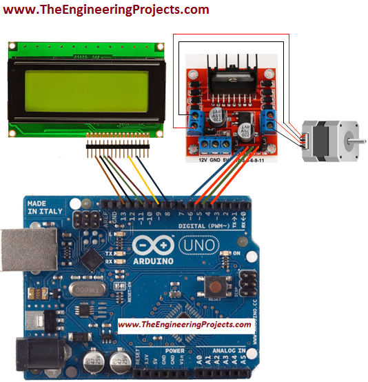
A brief introduction to Stepper Motor As mentioned earlier, a Stepper Motor is a type of DC Motor that rotates in discrete steps. Due to their unique design, stepper motors can be controlled for precise positioning without any feedback. A typical stepper motor has multiple coils that are divided into phases. When each phase is energised in sequence, the rotor of the stepper motor rotates in steps.

Basically, there are three types of stepper motors: Variable Reluctance (VR) Stepper Motors, Permanent Magnet (PM) Stepper Motors and Hybrid Stepper Motors. Based on the winding of the stator, stepper motors can also be classified as Bipolar Stepper Motors and Unipolar Stepper Motors. We will not go into the details of the types of stepper motors but it is important to identify whether your stepper motor is a bipolar or unipolar one.
This is because, the driving method for each of these stepper motors is different from the other. For instance, the driver circuit of a unipolar stepper motor can be implemented with simple transistor based circuit or a Darlington Transistor IC like ULN2003A.
Tags: Tamil Comedy Video Songs, Video, Tamil Comedy bollywood movie video, 3gp Tamil Comedy video Download, mp4 Tamil Comedy hindi movie songs download, Tamil Comedy. Tamil comedy scenes download mp4.
But in case of a bipolar stepper motor, we need to implement an H – bridge type driver like L293D Motor Driver IC. The following image shows a bipolar stepper motor, a 6 – wire unipolar stepper motor and a 5 – wire unipolar stepper motor. The most common step angle or step count for stepper motors is 1.8 0 or 200 steps (both of them are same as 1.8 0 x 200 = 360 0). How to Design Stepper Motor Control Circuit? In this project, we have used a bipolar stepper motor.